Creating a single surface from a thickness map
With the Surface from Map tool (prepare > Thickness Map > Tools) you can generate a surface (tri-mesh) based on a reference surface in combination with a thickness map. To do this, the following conditions apply:
- The thickness map either needs to be created with the JewelSuite Subsurface Modeling Thickness Maps workflow, or must be a surface of the type 'map' with a thickness property that is stored in the Imports folder or Data folder in the JewelExplorer. Such a surface can be imported from another application, or generated with JewelSuite. For more information, see Importing a thickness map created in another application.
- When using thickness maps created via the Thickness Maps workflow, the reference surface needs to be a surface (2D grid or tri-mesh) that was used (either as top or base event) during the creation of the thickness map.
You typically use the Surface from Map tool when you have a marker for which you want to create a surface, and where you want to control the lateral extension via the use of a thickness map. You can also use it to create a surface based on a thickness map that was created in another application. The form has two tabs. The Surface tab is where you fill in all the settings to create the surface. The Well Match tab is where you can select a marker set that is used for well matching the created surface.
Thickness maps themselves cannot be integrated into the Structural Modeling workflow or the 3D Gridding workflow. However, the surface created from a thickness map can be used in these workflows, if the event is assigned to the relevant stratigraphic model.
Surface tab
To generate a surface
- At the top of the form, select the source that contains the thickness map that you want to use (select from either Imports, Data or Thickness Maps).
- Form the Thickness map drop-down list select the thickness map that you want to use.
- If the selected thickness map is created in JewelSuite, the property entry field is grayed out. If the selected thickness map is selected from either the Data or the Imports folder, select the thickness property as property to use. If your selected thickness map does not have a thickness property you cannot use it to create a new surface.
- In the Input section, under Source, select the folder that contains the dense surface (tri-mesh or 2D grid) which will be used as a reference surface.
- Select the Reference surface from the drop-down list. When the selected thickness map was created outside the Thickness Map workflow, all surfaces of the source are available for selection. If the selected thickness was created with the Thickness Maps workflow, only the event(s) with dense data representation that were used to generate the selected thickness map are available for selection . This means that:
- If you generated your thickness map based on surface data (2D grid or tri-mesh), both events are listed here.
- If you generated your thickness map based on one event with surface data (2D grid or tri-mesh) and one marker event, only the event with the surface data is listed here.
- If you generated your thickness map based on two events which are both defined by a marker, and you have no dense surface representing the same event, you cannot use this tool directly (see The Thickness Maps workflow).
- Honor fault model is an analog to the option on the Assign Data form in the Thickness Maps workflow. Here you select whether or not the thickness map should react to the presence of faults. If you select a fault model, this means that all thickness values which are calculated by projection 'through' a fault plane are excluded during the generation of the output surface.
- In the Output section, the options available depend on the selected input thickness map. If the selected thickness map was created outside the Thickness Map workflow, select how you want to use the thickness map: insert it as a top with respect to the reference surface, or insert it as a base with respect to the reference surface.
- Select either the Data folder or a surface set from the Folder drop-down list to which you want to add the created surface.
- Target surface is the name of the output surface, which is the 'other' surface (than the reference surface) enveloping the input Thickness Map. This field is for information only when the selected input thickness map was created with the Thickness Map workflow. If the input thickness map was created outside the Thickness Map workflow you can type a name here.
- Close Gaps will determine whether the algorithm will use a 3D grid to close the gaps which may exist on the reference surface. Also, when using a fault model, the Close Gaps option will attempt to create an output surface that seamlessly fits to the faults. See diagrams below for more information.
- Generate only for non-zero thickness values ensures that for all locations where thickness is 0, the surface is not created. Checking this option will prevent two horizons from overlapping. It is recommended to check this option when creating surfaces from thickness maps, as it helps to get a better surface-surface truncation in your structural model and grid when these surfaces are used as input. It will help to prevent artificial thin cells creation in the grid which can create unwanted baffling for dynamic simulation.
- Optional - If you want to perform well matching, go to the Well Match tab and select a marker set. The default well matching method is IDW.
- Click Apply to save the changes and create a new surface and keep the form open, or click OK to save the changes on the form, create the surface and close the form. The new surface will be available in the JewelExplorer, under the selected folder.
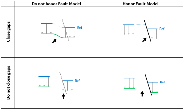
Schematic overview of the different outcomes when using the options 'Honor fault model' and 'Close gaps'. The example here uses the blue surface as the reference surface with a constant thickness map (not shown) for the purpose of creating the green surface as an output. Depending on the settings different outcomes are created. click to enlarge
Close gaps and do not honor fault model
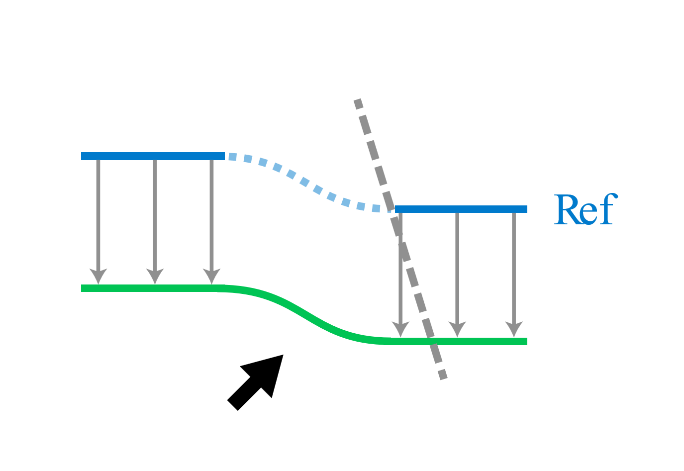
Diagram showing the results when 'Close gaps' is selected and 'Honor fault model' is not selected. Here, a green surface is created from the blue reference surface using a constant thickness map click to enlarge
When you select the option 'Close gap's but not the 'Honor fault model' option, the resulting surface (green in image above) will have a seamless output. If the reference surface is segmented, JewelSuite will first try to close the gap in the reference surface. Without the selection of a fault model, this may lead to flexures in places where fault gaps are present.
Close gaps and honor fault model
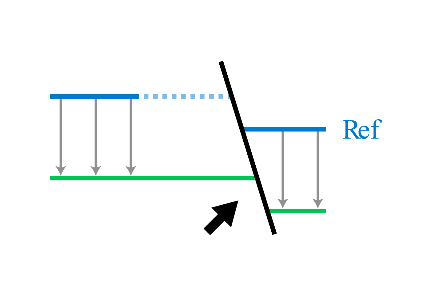
Diagram showing the results when 'Close gaps' and 'Honor fault model' are selected. Here, a green surface is created from the blue reference surface using a constant thickness map. click to enlarge
When you select the option 'Close gaps' in combination with 'Honor fault model', JewelSuite will use the gridding algorithm to process the input reference surface while honoring the selected fault model. For this, the fault model needs to be validated.
Do not close gaps, do not honor fault model
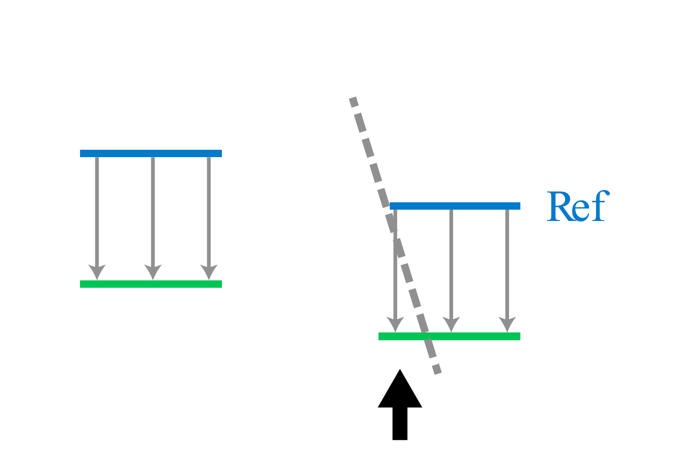
Diagram showing the results when 'Close gaps' and 'Honor fault model' are not selected. Here, a green surface is created from the blue reference surface using a constant thickness map. click to enlarge
When both options are unchecked, JewelSuite will not use the gridding algorithm, and ignore the effects of any faults. On locations of the thickness map at which the reference surface is present, the thickness is applied and an output surface is generated which can result in a segmented output surface.
Do not close gaps but honor a fault model
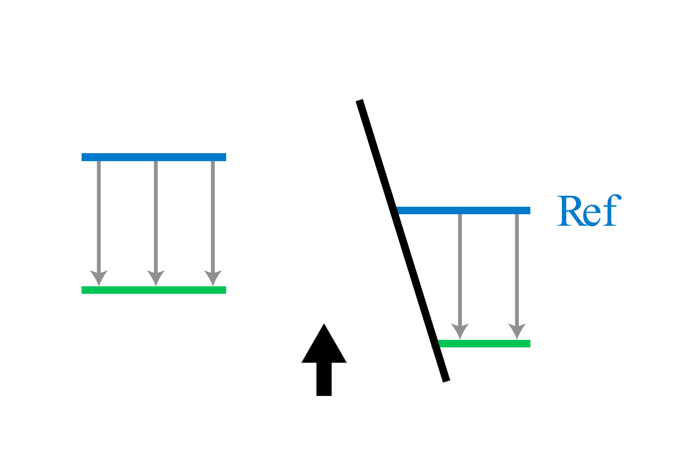
Diagram showing the results when 'Close gaps' is not selected but 'Honor fault model' is selected. Here, a green surface is created from the blue reference surface using a constant thickness map. click to enlarge
With the options 'Close gaps' is not selected and 'Honor fault model' is selected, segmented reference surfaces will lead to segmented output surfaces. When a fault model is selected, JewelSuite Subsurface Modeling tests whether the projection of the thickness is done across a fault. The thickness values which are projected through faults will be excluded during the generation of the output surface. This option may result in a surface with smaller patches as opposed to the other processing options.
Modeled example
See below an example in which two output surfaces are generated from a thickness map using the 'Honor fault model' option. The example on the left does not use the 'Close gaps' option, the example on the right does. For this, the left output has prominent fault gaps. Here, either the reference surface was not available, or locations are present in which the faults prevent a successful application of the thickness map, thus leaving behind these prominent gaps.
When you select the option 'Close gaps' (right image), a seamless output surface is generated. Using JewelSuites gridding technology, the surface will honor the fault model with the surface extrapolated against the faults.
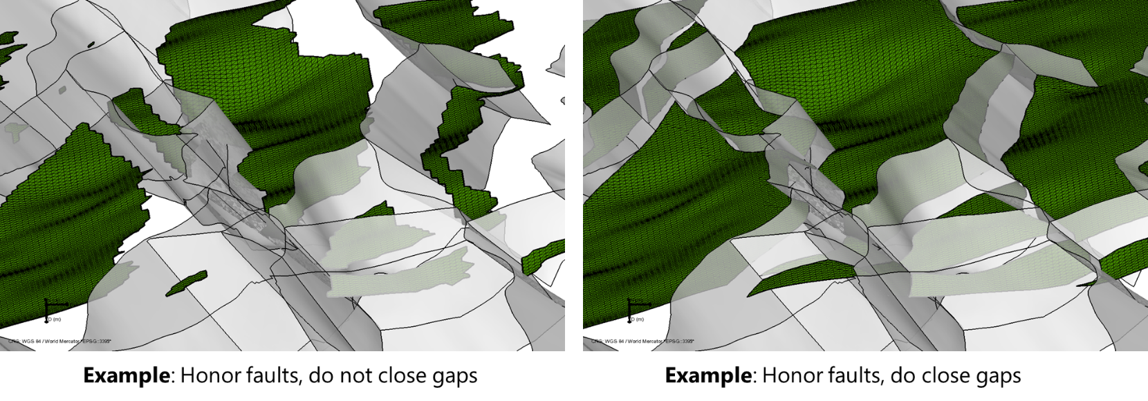
Side view on a model in which a thickness map is applied without (left) and with (right) the option 'Close gaps'. The output surface on the left only generates an output at locations where a reference surface is present and where the fault model is not violated. The output on the right uses JewelSuites gridding technology to generate an output surface that is honoring the fault model, extrapolating the surface to terminate against the faults. click to enlarge
Well Match tab
If you want to well match the surface, you can specify the settings on the well match tab.
From the Marker set drop-down list, select the marker set that you want to use for well matching. The default well matching method is IDW, but you can also select kriging. Click Apply to generate a surface and apply the well match and keep the form open, or click OK to generate a surface, apply the well match and close the form.
Importing a thickness map created in another application
Apart from using a thickness map that was created using the workflow available in JewelSuite Subsurface Modeling, you can also import a thickness map created in another application. To be able to use an imported thickness map to create a surface, you must perform the following steps:
- Go to data > Miscellaneous > Import Surfaces > 2D Grid to open the Import 2D Grid window.
- Make sure 'Files of Type' is set to the correct format and select the thickness map you want to import.
- Click Open. This will automatically take you to the Data Import Validation form.
- If the thickness map you want to import does not have a set CRS yet, use the Use solution CRS option on the form to assign one to it.
- From the 'Vertical Unit' drop-down list, select the Vertical Unit that is the same unit as the one used in the solution
- From the 'Type' drop-down list, select Map.
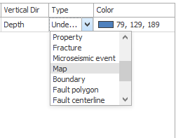

Select Map as the type of surface to import on the Import Validation form. click to enlarge
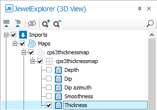
- Click OK to import the thickness map. It will be available in the Imports > Maps folder in the JewelExplorer and checked for display. If you have the 3D View open as the active view, or any other view where you can display a 2D Grid, you can see the imported map immediately.
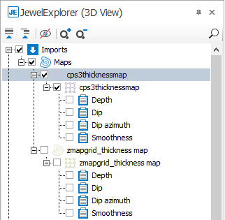

The imported thickness map is now available as a map in the JewelExplorer. click to enlarge
- To use the map as a thickness map, it must contain a thickness property. In other applications, the thickness might be available as a depth property. If this is the case, you must create the thickness property yourself.
- Select the Depth property in the JewelExplorer and use the right mouse button to open the context menu.
- From the context menu, select Duplicate to create a copy. This copy will have the name 'Depth - Copy'.
- Rename the Depth - Copy property to Thickness, and while this property is selected, open the Inspector.
- Click on Property type to activate the drop-down list and select Thickness.
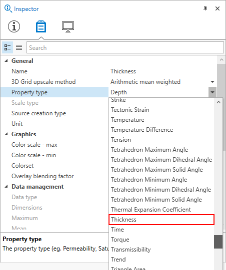

Use the Inspector to change the Property type. click to enlarge
- The map now has the Thickness property. You can use it to create a surface in the Surface from Map tool.

The imported thickness map is ready for use in the Tools section of the Thickness Map sub-strip. click to enlarge